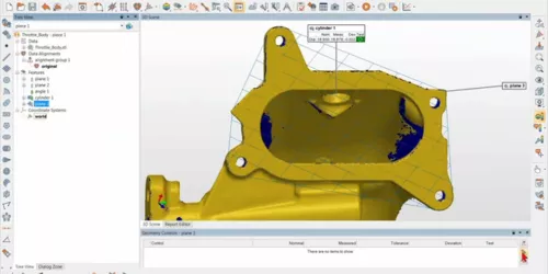
When a part is inspected with the help of its CAD model, the CAD model is used throughout the project to align the part, extract features, and produce pass/fail results. When inspecting a part by scanning without using a CAD model, you go through those same steps obtaining measured-to-nominal deviations but using a different toolset.
With the introduction of PolyWorks|ReportLoop™, a free Excel-based smart reporting solution, you can link spreadsheet cells directly to PolyWorks® inspection project data.
Inspecting a part in PolyWorks|Inspector™ with the support of a CAD model is not always an option. While using CAD models is a very efficient way of getting the nominal geometry required for performing an alignment, obtaining measurement deviations, and driving measurement guidance, when they are not available you can perform part inspection just as well.
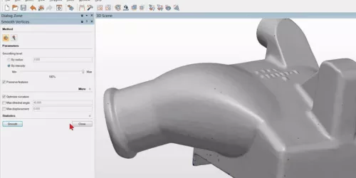
With PolyWorks|Modeler™ Light, quickly clean up surfaces, optimize the size of a model while preserving its topology and dimensional accuracy, and rapidly calculate volume and surface area.
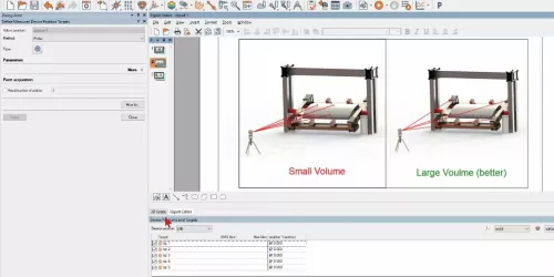
Whether you need to get a complete coverage of your part while scanning, or simply reach measurements that are beyond the range of your device, combining data from multiple part/device setups is a common task for metrologists. PolyWorks|Inspector™ offers a complete set of tools to efficiently and accurately combine data acquired from multiple device positions.
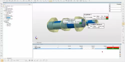
When facing complex metrology challenges, metrology specialists often develop in-house, proprietary measurement techniques that require documentation and support within their company. These measurement techniques can now be implemented directly within PolyWorks|Inspector™.
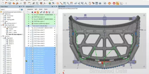
Creating CNC CMM sequences for projects containing a large number of measurement objects is typically a long process, involving repetitive tasks such as defining tool orientations, avoiding collisions, and finding the optimal object measurement order. PolyWorks|Inspector™ now offers an interactive sequence creation mode that assists users throughout the process.
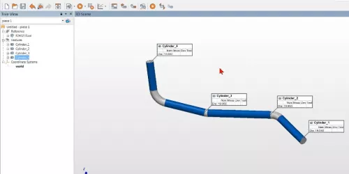
Custom bent tube and rod forms need to be measured to conform to the design callout from engineering drawings or tables. In addition, there is a need to document tubes and rods that have been created in the field, or highly modified for fit and function, as 3D models that can be imported into CAD software. Both the measurement and the CAD-creation operations can be realized easily using the free PolyWorks|Inspector™ macro, IMTube.
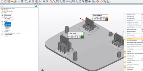
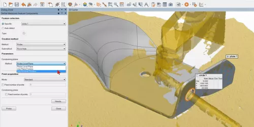
Inspecting thin parts made of sheet metal, plastic, or composite material poses a variety of challenges, whether you are using touch-probing or noncontact digitizing measurement tools. PolyWorks® offers a set of tools that facilitate thin part inspection as well as an application mode that presets values so your measurements are made with optimal parameters.

